Setting Up an RS-485 Network to a PC
RS-485 communication has been around for a while, but in case you’re just getting started, you may find the following information helpful.
There are four steps in setting up an RS-485 network to a PC serial interface:
- 1. Wiring
- 2. PC Serial Interface
- 3. Configure the Devices
- 4. Communication Software
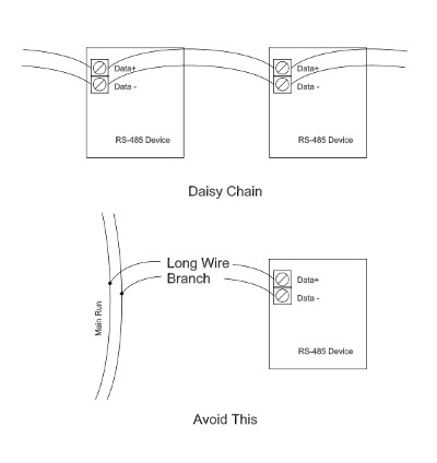
1. Wiring –The best approach is to simply wire in a “daisy chain”, starting from the PC interface, running one wire pair (half-duplex) or two wire pairs (full-duplex) to the terminals on the first device, then to the terminals on the next device, and so on down the line. If the PC is physically located in the middle of the run, then start at the device on one end of the run, wire toward the PC and then continue on to the other end of the run.

Wire RS-485 networks terminal-to-terminal in a daisy chain and avoid segment branches to reduce electrical reflections and improve transmission reliability
Remember that a maximum number of devices (usually 32) can be addressed on each RS-485 network and the maximum wire length is generally 4000 ft (1200 m). To minimize the effect of noise, use twisted pairs as in Category 3 or Category 5 cable, minimize wire lengths and avoid running parallel to power cables or near noisy devices (motors, relays, fluorescent lights). You should also avoid a long segment of wire branching off from the main run to one or more devices. It is better to simply extend the main run and double back.
Common Wiring Questions:
What is the difference between half duplex and full duplex? In order to transmit you need a pair of wires: one wire to transmit and one for a return, forming a circuit path. In half duplex, each device must alternate using the wiring pair to talk or listen, but not both at the same time. In full-duplex, a second pair is used, allowing devices to talk and listen at the same time. On the device, if only a single pair of terminals is available (for instance, Data + and Data -), then it is most likely a half duplex device.
Do I need a terminating resistor? At low data rates and short runs, the wire resistance (assuming 24AWG diameter wire or smaller) is often sufficient to cause settling on the bus between transmissions. As the length of the run increases or in a noisy environment, adding a 100 ohm resistor across the terminals of the devices at each end of a run (not at every device) may improve settling time and allow faster rates. Bear in mind that the terminating resistors electrically load the bus and may decrease the maximum length of your run, number of devices and data transmission speed.
What are Ground Terminals for? Most RS-485 interfaces, but not all (especially some USB to RS-485 converters), provide a ground, or “GND” terminal. This is used to connect to a similar “GND” terminal on other communicating devices. This terminal does not carry data or signal, but rather is intended to reference the data lines and remove common mode voltages. Without a reference voltage, the data lines may maintain relative (data transmission level) voltage levels between them, but their absolute voltages can drift out of electrical tolerance limits for the device. This can happen especially near high frequency, switched higher voltage loads, such as a variable frequency driven AC motor, for instance.

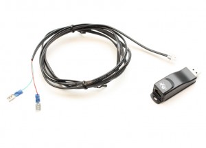
A USB RS-485 interface is an inexpensive option for laboratory, prototyping, or development work.
2. PC Serial Interface – A plug-in, PCI card interface such as the NI PCI-8433/4 that installed inside the computer is a good solution for adding an RS-485 serial interface, especially in an industrial setting. Other common options are USB-based RS-485 interfaces and RS-232 to RS-485 converters.
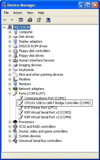
Regardless of the interface, expect to install a driver provided by the manufacturer to make the device show up on the computer as a serial port. On Windows-based operating systems, such as Windows XP, look in the Device Manager under Ports (COM & LPT).

RS-485 serial port installs in Device Manager on Windows OS
3. Configure the Devices – Depending on your device, this is usually done via the front panel menus. Assign a unique address (1-31) to the device and use the same serial settings on all devices. You may also need to enable serial communication on the device.
The most common serial settings are:
- Protocol – Most common is RTU mode; this may or may not be configurable
- Baud Rate – How fast bits travel on the wires, such as 9600 bps (bits per second)
- Data bits – 8-bit (text) is most common, but 7-bit binary is also used
- Parity –One bit can be set aside as a check bit (Even or Odd) or No parity used
- Stop bit – How many bits (0,1,2) are used to signal the end of a transmission
- Flow control – Commonly unused in RS-485 networks
An example configuration is 9600 baud, 8-bit data, No parity, 1 stop bit.
4. Communication Software – On a desktop PC, almost any software development environment includes tools for communicating through a serial port. A terminal emulator (like Hyperterminal on Windows OS) can be useful in taking the first steps. Many manufacturers provide free software with their devices that can be helpful for starting out.
For developing a custom application, National Instruments LabVIEW provides a graphical environment and is easy to configure. If using a supported process controller, you can incorporate the Process Controller Communication Libraries for LabVIEW for simple, “drag and drop” development.
For MODBUS ® capable devices, the MODBUS Library for LabVIEW is also available. In an OPC environment, an OPC server such as National Instruments’ OPC Server is required.
A basic PC-based program consists of these steps:
- Setting up the serial port: Usually done once at the beginning of the session. Use the same serial settings (baud rate, etc) on your PC as the other devices.
- Transmitting a data request: This is usually done by sending a formatted string of text to the serial port, usually including the device address, a command, a device register and/or data. Consult your device manual.
- Waiting for a reply: RS-485 communication usually requires the bus to be quiet for a specified period of time between communications. Wait times between transmission and reply are on the order of 10-100ms.
- Receive the reply: Interpret the string of text received at the serial report to extract data, configuration values, etc.
- Close the port: After setting up the serial port, transmissions can be repeated as many times as needed for a session. When the session is complete, issue a command to close the serial port so it is available to other applications.

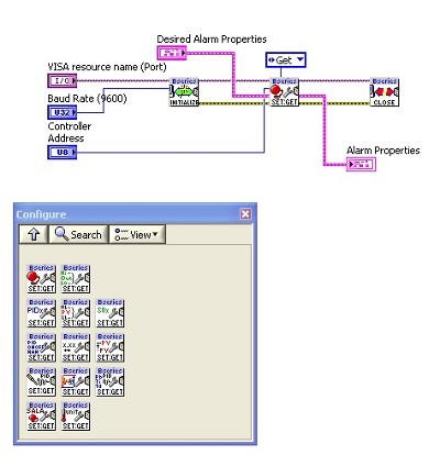
This simple example with the Process Controller Communication Libraries for LabVIEW implements a complete serial transmission. The block on the left initializes the port; the middle block transmits, waits and receives the data; the block on the right closes the port.
Remember that this is just an introduction to setting up RS-485 communications, so you may want to consult someone with experience or search the internet. Here are some links to additional resources on the web that you may find helpful
National Instruments Serial Quick Reference: http://digital.ni.com/manuals.nsf/websearch/4C402EAD9537B78C8625727200614412
RS-485 Serial Communication FAQ: http://integratedpro.com/content/?p=629
B&B Electronics Serial Reference: http://www.bb-elec.com/technical_library.asp
10 Ways to Bulletproof RS-485 Interfaces: http://www.national.com/apnotes/RS-485.html
